|
LABS:
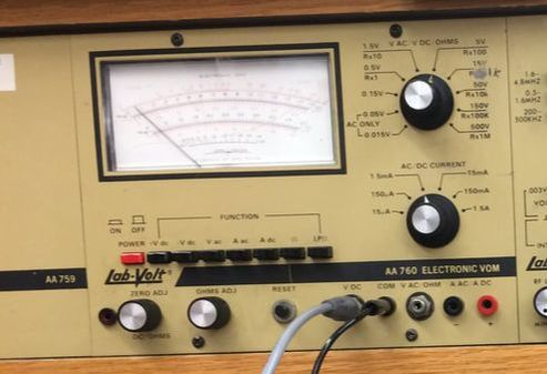
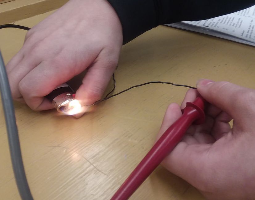
Lab 1: Safety; use of power sources and meters Overview: This lab taught me all about safety in working with electronics. Such as how 100mA can kill you. I also learned how to measure resistance by measuring the resistance of myself using the electronic VOM. In measuring my resistance, when I put water on certain areas of myself then measured the resistance, it was much lower than it used to be. This shows that if I am wet and I get electrocuted, the damage done could be a lot worse than usually since the current would have any easier time flowing through me. After that I learned how to measure and set the voltage coming from the power supply by measuring it in parallel with the volt function on the Electronic VOM. I also learned that the ammeter is supposed to be connected in series in a circuit. This lab also slightly introduced me to parallel/series circuits by showing me the difference of when the load is connected in series or parallel. Lab 2: Component Symbols and Abbreviations This lab taught me that schematics are very important when being an electrician as they give specific detail on how the load is hooked in. Some of these details, such as polarity, could be difficult to portray in a pictorial or other diagram. This lab got me familiar with multiple different schematic symbols by viewing a circuit, and matching the schematic symbols in the circuit with what the symbol represented, which was stated on another page. I also learned that many people working in electronics use abbreviations instead of the full word. I learned over 16 abbreviations by matching abbreviations with the full word, and matching the full word with the abbreviation. The abbreviations and their full words were stated on another page. Lab 3: The Electronic Vom This lab built off of lab 1 where I learned a little more about the electronic Vom. I measured resistor values, and I read different scales for current, voltage, and resistance. Then I learned how to properly connect different functions of a Vom into a circuit, such as how a voltmeter must be connected in parallel. I also learned that you need to zero an ohmeter, and the correct test leads for each function of the Vom. Then I learned that a voltmeter can input a low resistance into a circuit by comparing the loading effect of a panel voltmeter to the Vom. Lab 4: Sources of Electricity In this lab I hooked up a thermocouple to the Vom on the +DCV setting, then increased the temperature of the thermocouple with a lighter. When I did this, the heat was able to be transferred into a few milivolts by the thermocouple. After this I hooked up a solar cell to the Vom. The solar cell read about 100 miliVolts. When I placed my hand over the solar cell, therefore not letting it be exposed to light, the voltage decreased. When I placed the solar cell near a lamp that was on, the Vom read that there was more voltage coming from the solar cell. After this I found out one of the basic properties of a series circuit, which is that if cells are in series, the voltages of the cells are additive, but if I place them in parallel and connect the voltmeter, I only get the voltage reading that only one cell is connected. Lab 5: The Electronic Power Supply This lab taught me about how the power supply works, and not just how to use it like the previous labs where I needed to build a circuit. First I built a circuit with multiple resistors in it, then noticed that although current and power demands an increase, the voltage being outputted by the power supply remained the same. I then added more load to the circuit, and learned that whatever voltage changes that do occur are called power supply load regulation, and I was able to later calculate that. Knowing this of a power supply can help make future circuits of mine more accurate. Lab 6: Switches and Switching Circuits This lab had me connect multiple different switches to lamp(s), then I would flick the switch to see what would happen. I also hooked up multiple switches in one circuit to expand my knowledge of what could be done with switches. In this lab I learned the differences between how many different switches work, such as the DPDT switch, the PBNC switch, the SPDT switch, and the DPST switch. I also learned about the switches schematic symbols and how they correspond to what position the switch is in. Lab 7: Ohm's Law This lab taught me Ohm's law by calculating either voltage, resistance, or amps using ohm's law when knowing the other two values, then building a circuit, putting in those two values, then connecting the Vom to read the value. In this lab I learned about how to calculate ohm's law and I got to see it how it worked on the equipment. I also had to read resistor color codes which is a skill that took me a while to fully master. Lab 8: Power-Heat-Light In this lab I calculated current flow and power dissipation for multiple different voltages. Then like in many other labs, I tested what I calculated by creating a circuit and applying those values. If my measurements were similar to what I calculated, I would know that I calculated it correctly. After this I placed a lamp into a circuit and started to change values, and observe the measurements to learn some concepts on electricity. I learned about what Watt's law is and how to make use of it, such as observing patterns between current, voltage, and power. For example if both current and voltage is doubled, then power is quadrupled. I also learned that as current flowing through a lamp filament increases, more power is dissipated in forms of heat and light. I also learned that resistance is increased as a resistive substance's temperature increases. Lab 9: Series Resistive circuits In this lab I identified whether or not a circuit was in series. Then I created some resistors in series and measured the current flowing through them when a source was connected to them, how voltage changed from each resistor, and how resistance changed when they were connected. In this lab I learned the basics of how electricity works in a series circuit. I learned that voltage drops after passing through a resistance, current flow is the same throughout a series circuit, and that resistance is additive in a series circuit. Lab 10: Series Circuits-Kirchhoff's Law This law expanded what I knew about series circuits by teaching me what Kirchoff's law is. I created a circuit with different resistors, then I calculated/measured the voltage drop along each resistor. When those values are added up, they equal the total voltage that is being flowed into the circuit. That is Kirchoff's law, and how I learned it. After this I hooked up a potentiometer and did very similar measurements as last lab. After this I found an unknown voltage drop value of a potentiometer by using Kirchoff's law. This lab taught me all about Kirchoff's law, and also how to connect a potentiometer. Lab 11: Parallel Resistive Circuits This lab was very similar to "Series Resistive circuits", but this time I learned the concepts of a parallel circuit. In this lab I identified multiple parallel circuits. After this I calculated what the resistance of multiple resistors hooked up in parallel would be. Then I connected resistors in parallel and measured the resistance. After this I measured current and voltage throughout my circuit. In this lab I learned how how to identify parallel circuits. Next I learned how resistance, current, and voltage behaves in a parallel circuit, and how it is very different compared to a series circuit. I also learned that I could figure out missing values in a parallel circuit by understanding the formulas of how electricity works in a parallel circuit. Lab 12: Parallel Circuits-Kirchhoff's Law This lab was very similar to lab 10, but in this lab I learn about Kirchoff's law in a parallel circuit. In this lab I created a three branch parallel circuit, then measured the current of each branch. When I measured the total current, I learned that each of the current values of each branch add up to my current total. I then used a potentiometer to further verify this like in lab 10. Lab 13: Series-Parallel Circuits In this lab I learned how to connect series parallel circuits together by connecting series parallel circuits. I then calculated values such as total resistance and current, and then made sure my calculations were correct by measuring it with the electronic Vom. This lab taught me everything I needed to know when there were components in series and in parallel in the same circuit. |

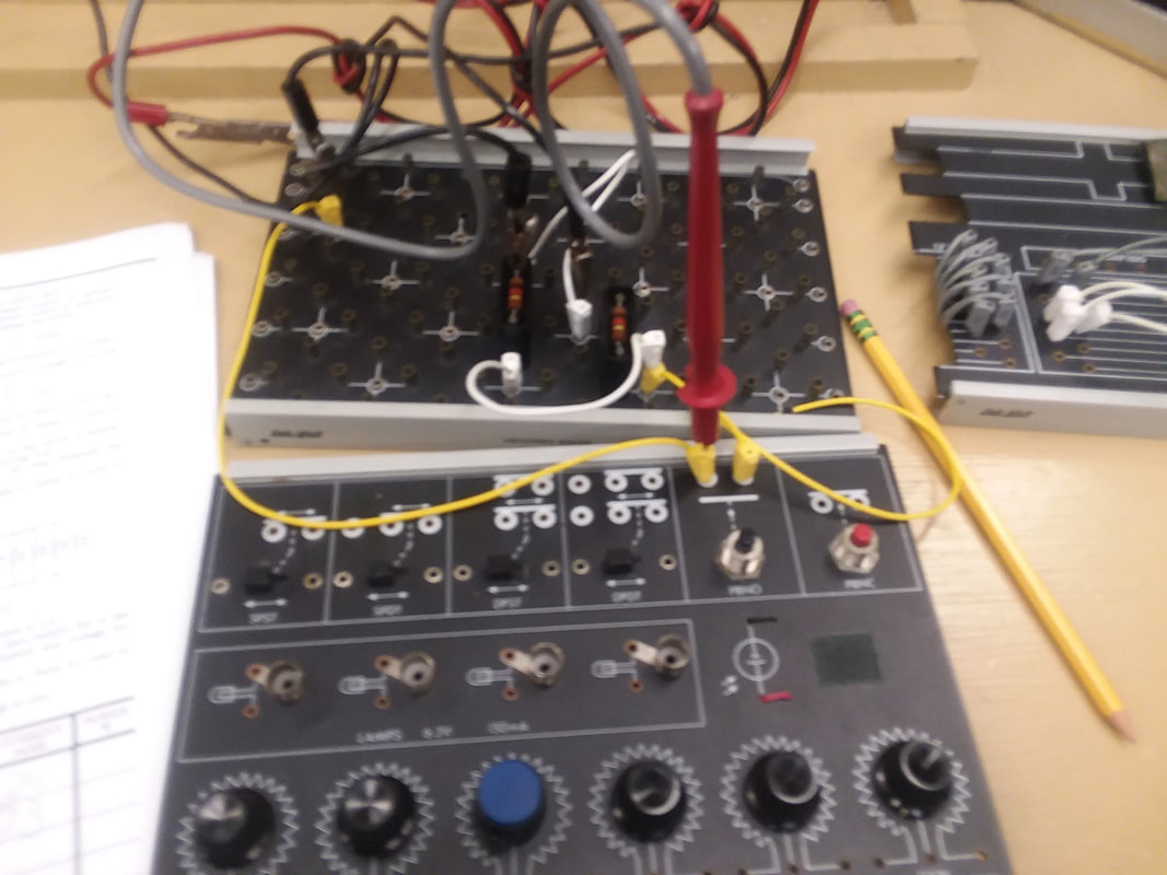

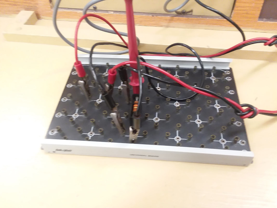

Series Circuit
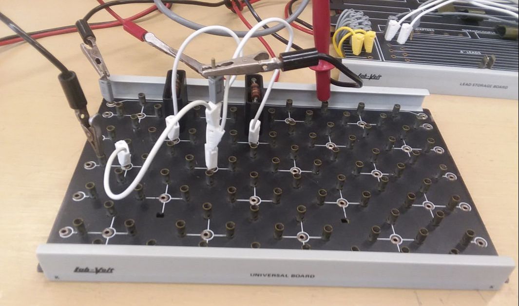
Parallel Circuit
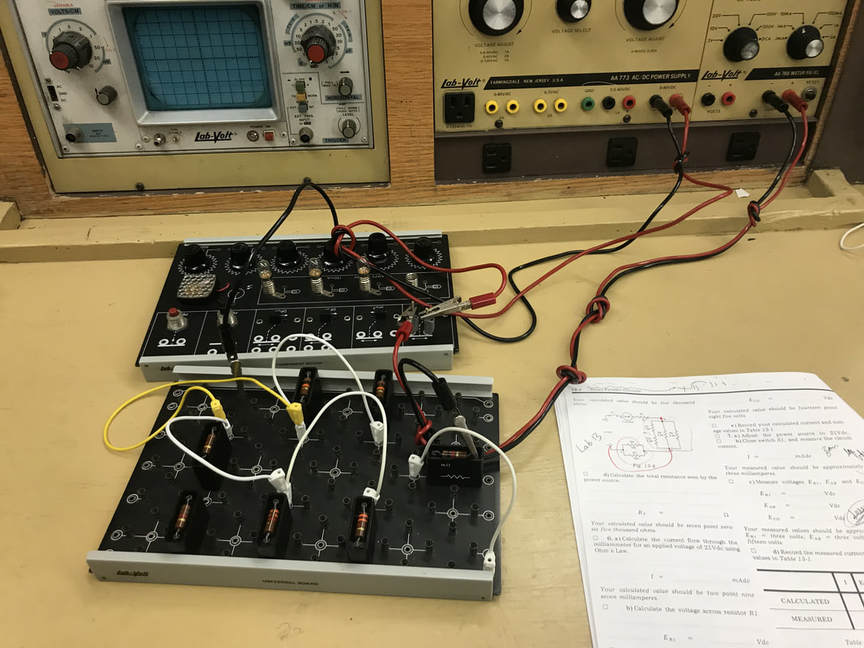
This photo of the Series/Parallel lab was taken by Jenny
|
